Robot' Modularity
Modularity in the robotics is very important concept. Jasmine III and next versions are completelly modular. To provide compatibility of the whole platform please take into account the following considerations for development of extension boards:
- Geometical considerations:
-
Upper-extension boards can be connected to the main board by using PORT1 and PORT3, the lower-extension board uses PORT2. Make sure that the position of connectors in extension boards coinsides with the main board.
- Leave a small gap in the center of the upper-board for providing IR-signal from remote control to PCM sensor (min. diameter 5mm), other case robot cannot be controlled by remote control.
- For lower-extension boards: please consider geometrical restrictions from gears.
-
Geometry of extension boards is free, however it should not ovestep the boundary of the robot as a square of 28x28mm, for lower-extension boards - the geometry of chassis.
-
- Electrical considerations:
-
The upper extension board should not consume more than 50 mA current from regulated power line and avoid using of non-regulated power line (try to minimize the power consumption as much as possible). Non-regulated power line in PORT1 is always on (even when robot is switched off) and is destined only for advanced power management. Extension boards destined for advanced power management should have power switchers on this line and generally consume no more that 100mA.
- Lower-extension boards should not consume more than 50 mA current from regulated power line and 100mA from non-regulated one (it is off when the robot is switched off).
- The peak of power consumption (at most 10 ms duration) should not overstep 100mA and 200mA correspondingly.
-
The board should possess capabilities to power-down mode (like those in Atmel microcontrollers) with week-up from the TWI interruption by the general call. Power consumption in power-down mode should by less than 1mA.
- The extension boards should not put any passive capacitive elements on TWI bus (SCL and SDA pins). Capacity of active elements should by no more than 20pF .
- The extension boards should not put pull-up resistors on TWI bus (SCL and SDA pins), they are already in the main board (2K each).
-
- Mechanical considerations:
- Extension boards should use round-shape 1.27mm-step connectors. Pin 8 from the PORT1 connectors should be removed (this is the mark pin).
- Logical considerations:
- Extension boards should use TWI logical interface.
-
Each extension board should have unique slave-address (now: 1 - the main board, 2 - the motion board, 3 - the GPS board) and support the genaral call (address 0). In generall call each board should have the command 255 for going to power-down mode and the command 254 for wake-up.
- Transmission on the TWI bus is of one, two or more bytes, however try to minimize the transfer on TWI bus. Preferred is the multi-master communication mode (see more in TWI).
- Use the clock frequency of SCL line as defined by TWBR=11; (prescaler=0). It puts TWI bus on 210526 kHz.
- Write handlers to all events defined by TWSR register (see more in TWI section).
- Commands from different extention boards to main board should not be in conflict. Therefore reserve the commands area for the developing board (see more in TWI section).
- Organizational considerations:
-
From the begin of development describe your board (purpose, main capabilities) in the corresponding section of swarmrobot.org. This is especially important to avoid unnecessary efforts on developing similar extension boards. Put estimated power consumption from power lines (to see the overal power budget of the robot).
- Put slave-address of the extension board in the table in section TWI.
- Reserve the commands area in the main board (corresponding table in section TWI).
- When the board in finished (tested), put images, electrical schemes, PCB desing and code-source in the corresponding sections.
-
1. Geometrical considerations
Geometry of the robot is rescricted by a few geometrical limitations. The most serious of them are motors (21x6mm) and accu (23x25mm). Therefore when we are still using them the robot cannot be reduced in a size. The minimal size of the robot is about 26 mm, however Marc means that absolute minumum is 28mm (Marc please comment). The picture below demonstrates top of the main board III.
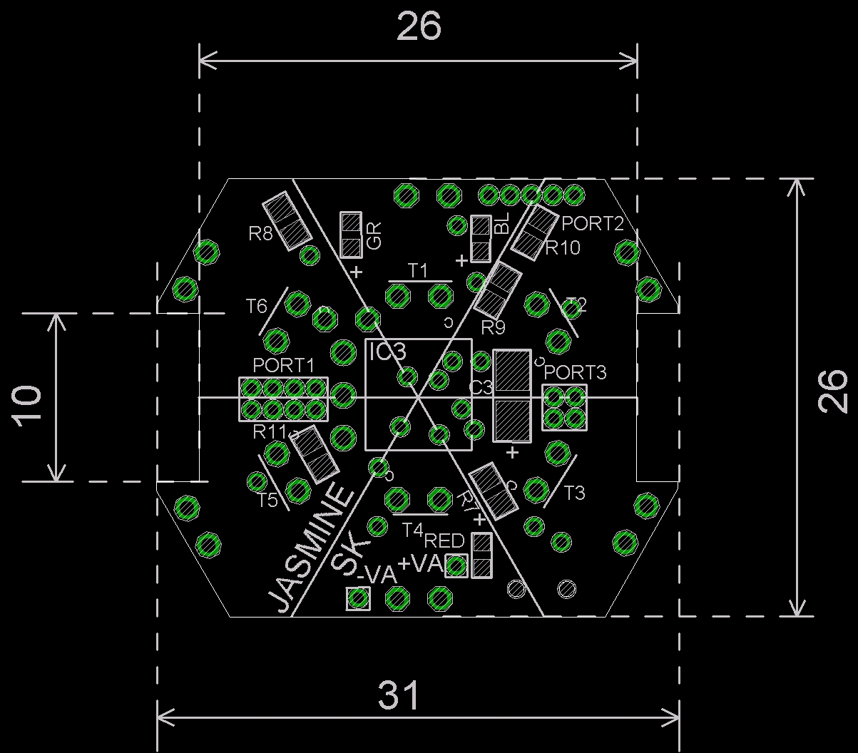
We need three different ports: PORT1 (for upper extention boards: TWI+serial interface + accu recharging+powering), PORT2 (for lover extention boards: TWI+powering), PORT3 (for upper extention boards: ISP + reset (reset is configered as a port)).
2. Electrical Considerations
PORT1:
- GND
- regulated +3V
- direct link to 4.2V accu (before power switcher)
- TXD
- RXD
- SCL (TWI)
- SDA (TWI)
- closed as polarity pin
PORT2:
- GND
- regulated +3V
- non-regulated 3,7V after power switcher
- SCL (TWI)
- SDA (TWI)
PORT3:
- reset (port)
- SCK
- MISO
- MOSI
All modules need regulated and nonregulated voltage (?) and TWI bus (?). Pull-up resistances should be soldered only one time in the main board (there are now 2k each).
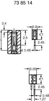
3. Mechanical Considerations
In the design connectors N 738530 are used. Connectrors are broken into suitable parts manually.
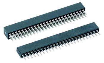 |  |
When you have better solution (Colin Monty) ...
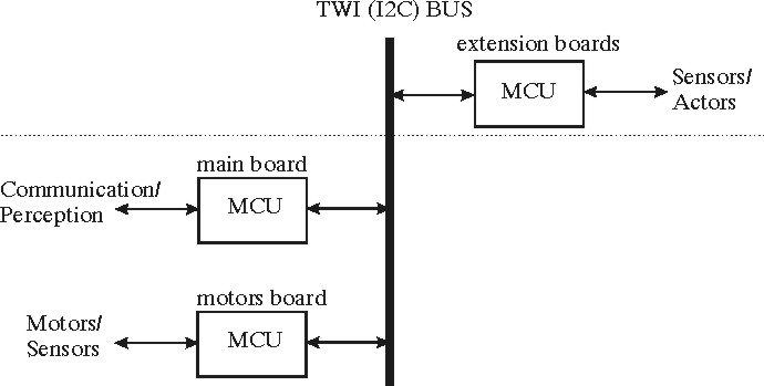
4. Logical interface (TWI)
Robot is "logically" connected by using TWI bus (analog of I2C bus).